Redox Handwire Iteration 3
So, as I previously blogged about, I’ve been using a Redox Handwire keyboard build .
As it turns out, it is not so nice to have easily removable microcontroller connections on a keyboard. The jumper cables kept coming off, which was a nightmare for typing.
So I had done a second version, which I didn’t write about, because I thought it was too similar to the first.
Basically all I did was add a small breadboard for the microcontroller to sit on, and which held the connections more steadily. But that was about it.
Now, even this iteration of Hackie (as my wife and I affectionately named the Redox Handwire) started getting very flaky. Keys would randomly fail, and sometimes just get disconnected. This was very irritating, and eventually got to a point where I decided I needed to address this.
New plan
So my new plan for this update of Hackie was two things:
- I had learned some lessons from the previous rounds of building Hackie. One of the biggest problems I faced was that keys would randomly disconnect, and I suspected it was because the wire connections were coming loose. So, this time I would tightly connect the wires before soldering them.
- I realized that a moving part outside of the keyboard meant a lot more problem, so I wanted to be able to fit the microcontroller into the case.
Better wire connections
The first part was not so hard, but very tedious. I basically had to wind the wires around each other before soldering them, which was very cumbersome and such fine work.
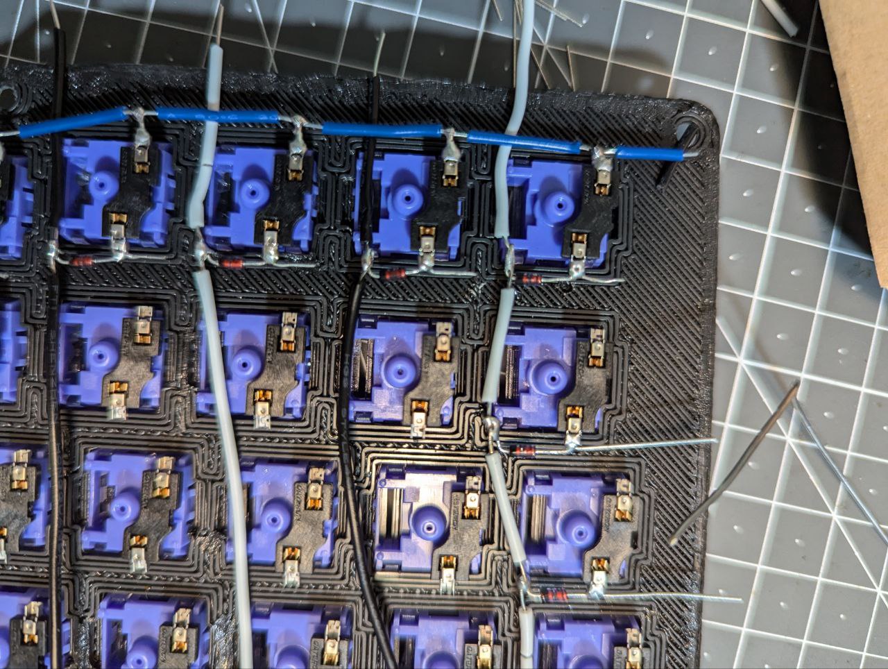
I also decided to do all the rows at once, which would sit closer to the plate, and therefore could be done first.
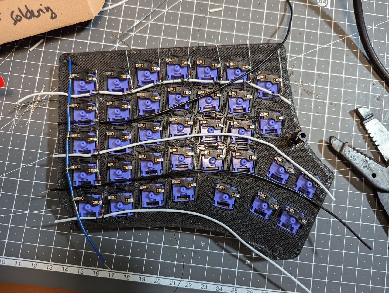
I don’t know if this will solve all the problems, but I do expect to get fewer of the same sort of issue arising from loose solder.
Microcontroller placement
I figured the best place to put the microcontroller would be inside the case. This was not so much of a problem, but it did mean I needed some way for the microcontroller to sit securely when plugging in, or removing the cable.
In the end I decided I would just melt a channel into the case, since it was a 3D Printed case.
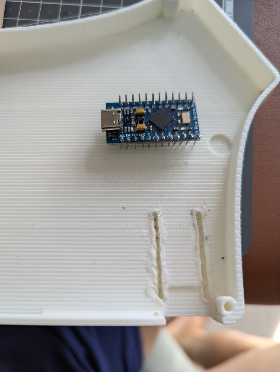
This turned out okay, and the microcontroller could sit almost flush to the case.
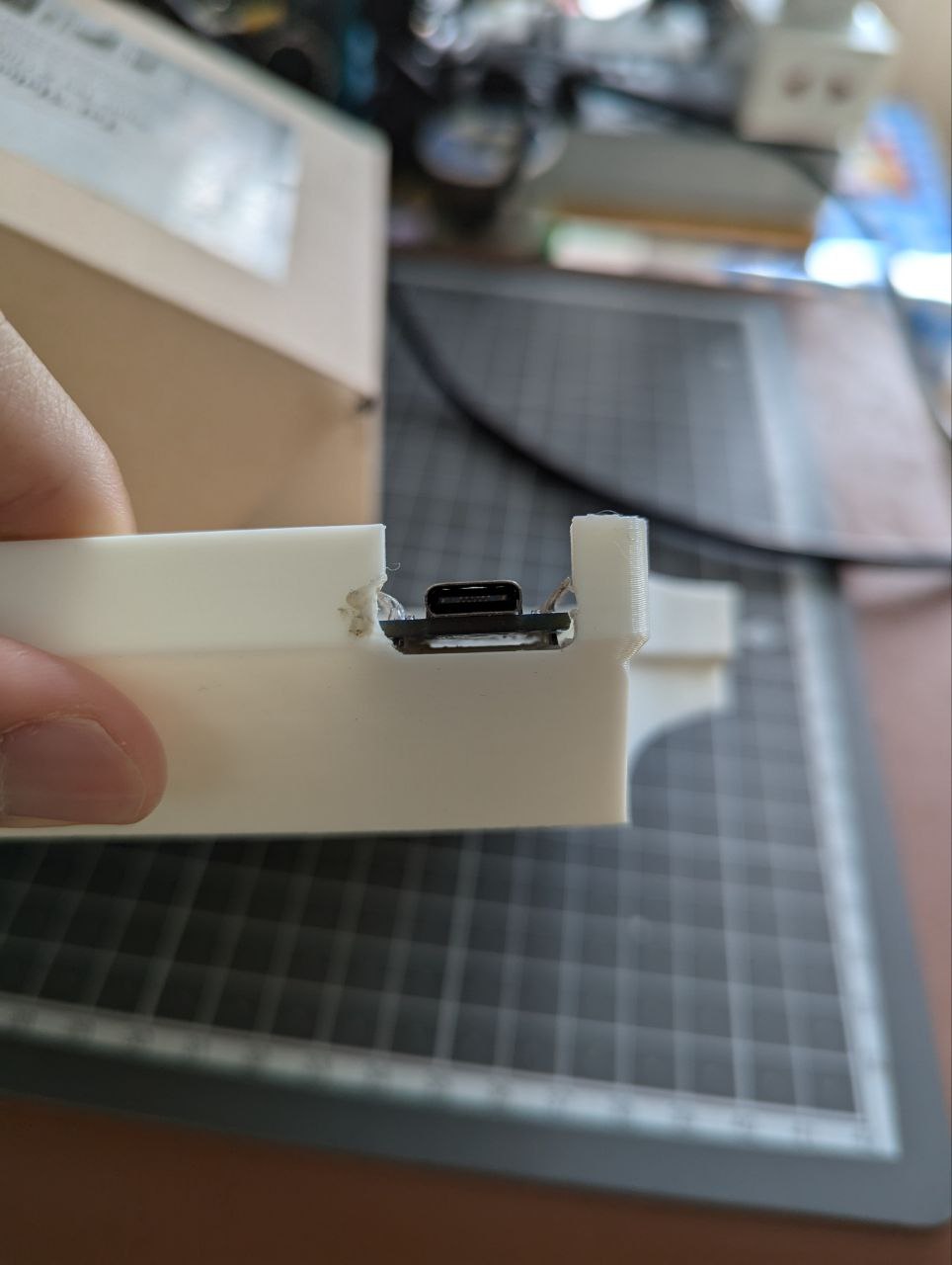
This wasn’t the prettiest, but it was quite easily doable, and it worked.
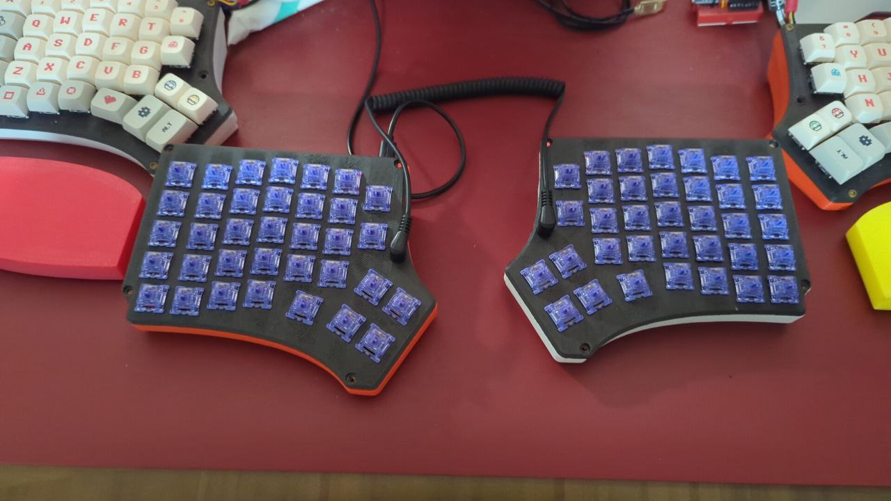
Finished v3
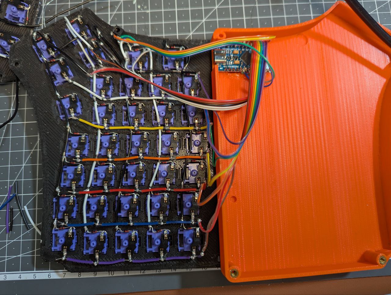
So finally I finished all the wiring! This round was a lot neater than previous rounds. I decided to mix wires this time, instead of using only single core wires. Instead, I used some Ribbon cables for connections between the keyboard matrix and the microcontroller, which lent a lot more flexibility when the case is closed.
Some trouble with QMK
I had a little trouble with QMK too. For one thing, I forgot the steps needed to flash the firmware correctly to both sides.
As it turns out, I could use QMK Toolbox, but I could not use the .hex file compiled by QMK Configurator. That’s because I needed EE_HANDS defined, and this had to be done in the C code itself.
But once that as done, I could just flash the EEPROM for left and right hands, and then flash the compiled .hex.
This worked just fine, and I’m now typing this on my new and improved Hackie v3. I do have plans for Hackie v4, but it’s still in the works, so I’ll share it when it’s ready