Redox Handwire Iteration 4
As is my custom, I am writing this post with my newly minted Redox Handwire Keyboard V4. I’m proud of each of my attempts, naturally, but most proud of this latest one, because it encapsulates the many hours of design iterations that have gone into this particular version.
Version 1 was my very first foray into the Redox keyboard, and I really fell in love with it. It was open-source, split, erogonomic, and I could build OR buy!
Version 2 wasn’t blogged about; it was simply a re-build of Version 1 with very little improvement. I actually re-did the wiring on this version several times, partially because it was just so wonky, and partially because I was using a breadboard.
The skeleton of Version 2 now serves as a reminder of the best place to start my new builds.
Version 3 was my latest in the line of really incremental changes, and it resulted in the most electronically stable keyboard so far; I actually use it as my daily driver at the office!
Version 4 combined a lot of my learnings to create a new, iterative ideal:
- Internally, the fewer soldered parts, the better; ideally, parts should be directly connected to one another and not through another wire.
- TRRS requires another hole, and connectivity is sometimes a problem; USB-C would be ideal.
- Frequent plugging in and out leads to loose connections; ideally, we’d have a mounted part for the microcontroller and USB-C connectors.
- Low-profile keys would be nice if possible.
- Wrist-rests should be touching the keyboard for easier alignment but also be large enough to encapsulate the palm.
I already knew how to solve point 1 by Version 3, and I had some ideas on how to do this with Version 4.
Similarly, a little research and thinking was able to address point 2 quite easily; 4-pin USB-C would work the same as TRRS for communication between the halves. At least electronically, this wouldn’t be a problem, but I had to figure out where to put that USB-C.
It was point 3 that took me a while. This, in conjunction with the new USB-C, required that I carve out a larger portion of my case to make space for a mounted board. That, and I had to find a mounted board first.
I did some searching and found a suitable board online which would accommodate the Arduino Pro Micro that I use.
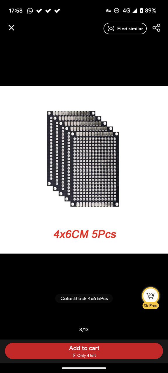 The PCB plate I ordered from Aliexpress.
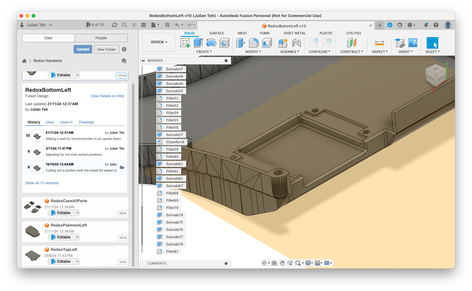
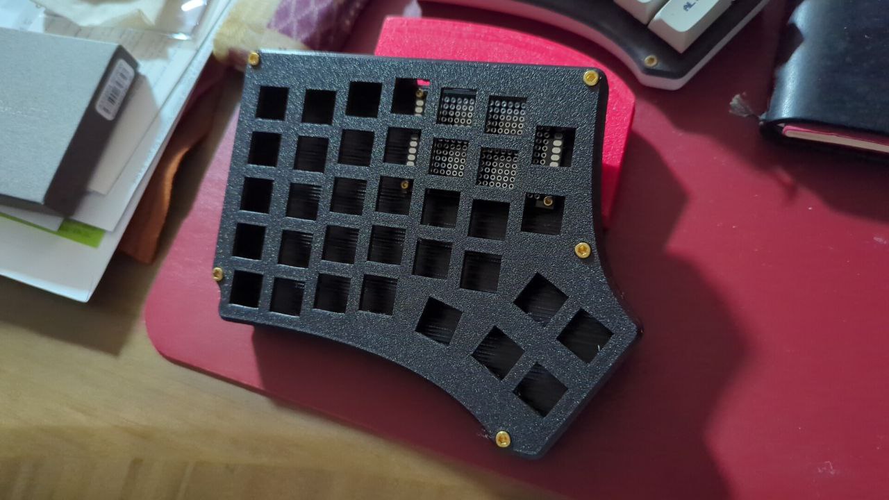
While I waited, I did some CAD work with Fusion 360 to modify the original Redox Handwire V1 case to my liking, adding tilt, reinforcing, the wider cutout, and wrist rests.
 The reinforced plate design in CAD.
Since I wanted low-profile switches, I also had to use low-profile hotswap sockets, which had a very slightly different positioning. This also meant that my reinforcing strips had to take these positions into account.
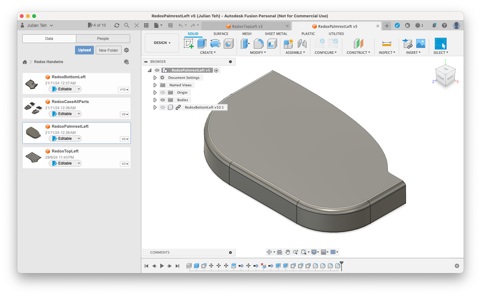 Extended wrist rests in the CAD model.
And of course, the wrist rests were extended accordingly, and I chamfered the edges for a more comfortable resting point.
Once the parts came, I was able to do a test fit.
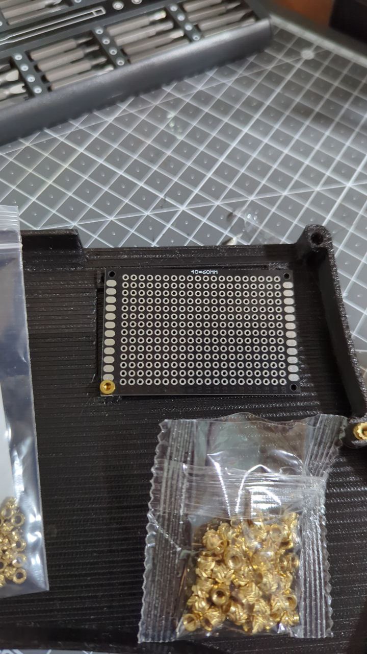 PCB plate parts and hotmelt sockets ready for a test fit.
And there the problems began. I was off by half a millimeter in one direction or another, and it took me several tries (my mentee, who was 3D printing the parts for me, was a little incredulous to find out that I didn’t have vernier calipers) to get the dimensions right.
 An early test mount for the PCB.
I learn a lot through these projects, a key lesson being to think differently when doing hardware. With software, I can just… well, copy parts that I want. But with hardware, it is useful to isolate the part that I want to measure and fit, and make sure that part fits in isolation before I start to integrate other pieces.
On top of fitting the PCB plate, I also had to worry about whether I had enough overhead from the PCB plate to the wiring above; if that touched, it would cause a ghost key effect, which I had seen in my Version 3.
 Modifying the CAD for socket cutouts to ensure clearance.
So, I had to also modify the CAD design so that the microcontroller and USB-C sat below the PCB plate, giving plenty of room for the wiring above it.
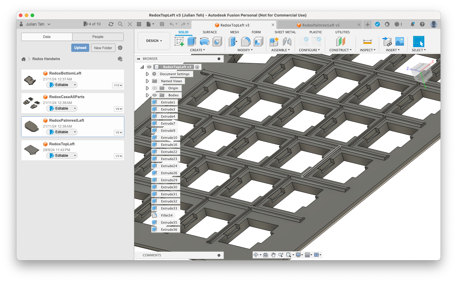
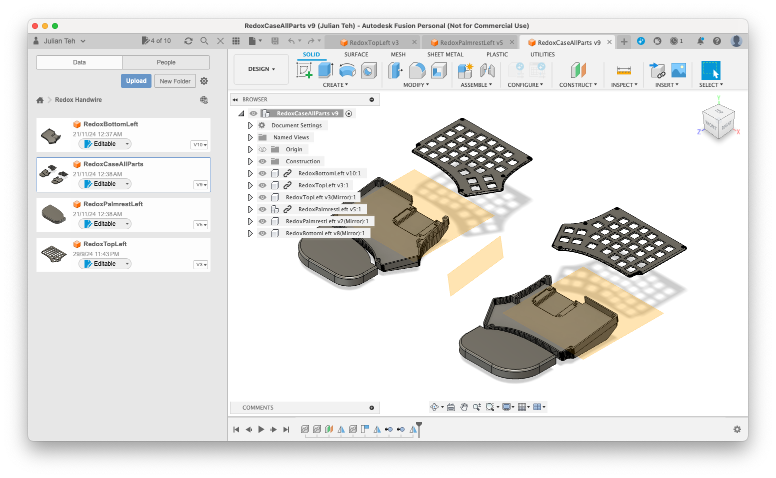 The finished CAD after many revisions.
The final CAD looked like this; as you can see, this was 10 versions of changes, between very small position changes and large cutout adjustments.
 Finally, a successful test fit of the PCB plate!
Finally, all the fitting had been done, and I could move on to the actual soldering.
This was arguably the easiest part; of all the changes I had made, this was the part I had done many times over. Even so, when I started, I realized a small but key difference in the hotswap sockets which made me quite happy.
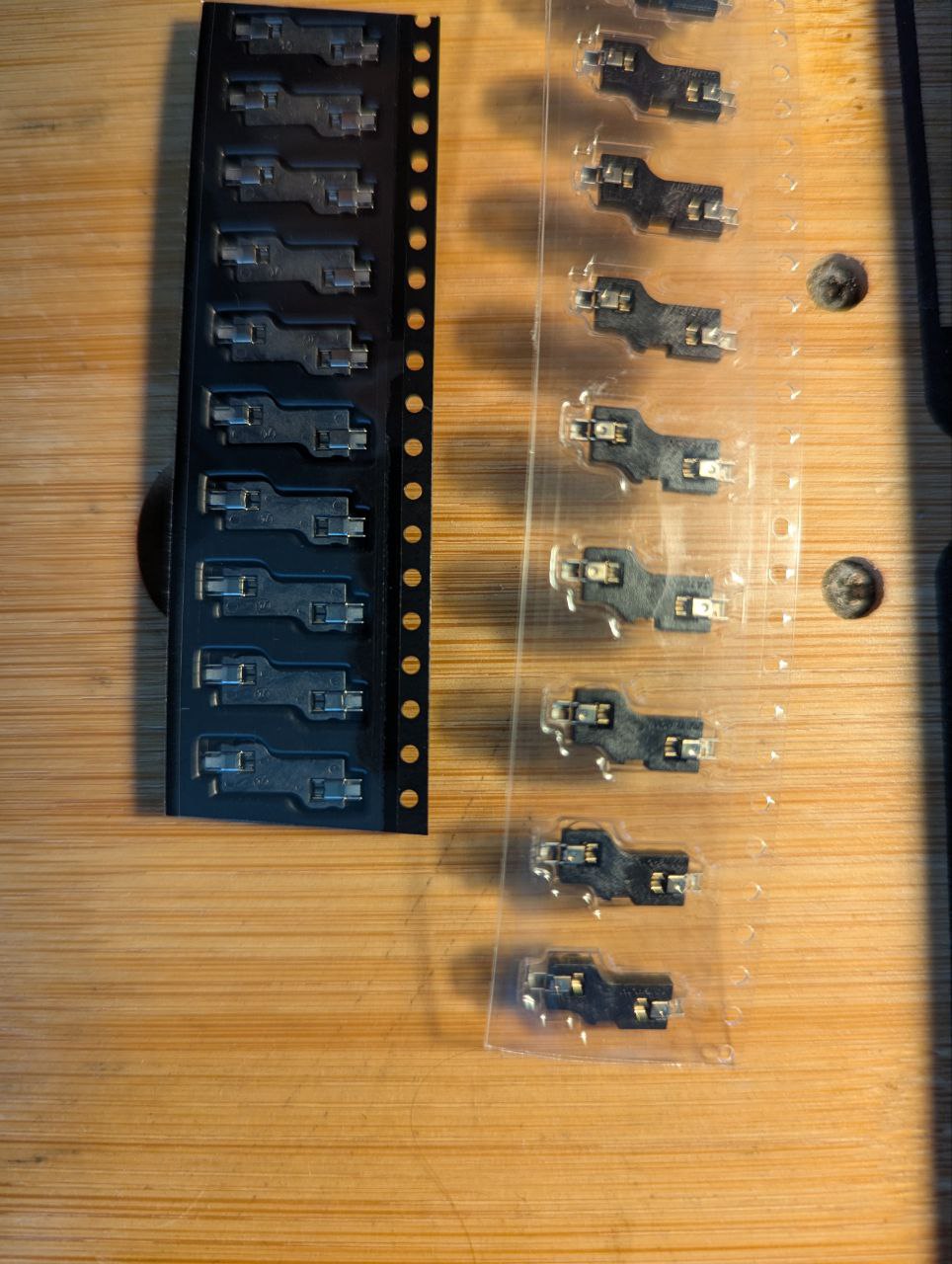 A comparison: low-profile sockets (left) vs. standard ones (right).
Notice how the ones on the left – the low-profile sockets – have a 4-sided channel, instead of the 3-sided channel in the ones on the right? This is very useful for holding my little wires in place and ensuring contact while soldering and afterward.
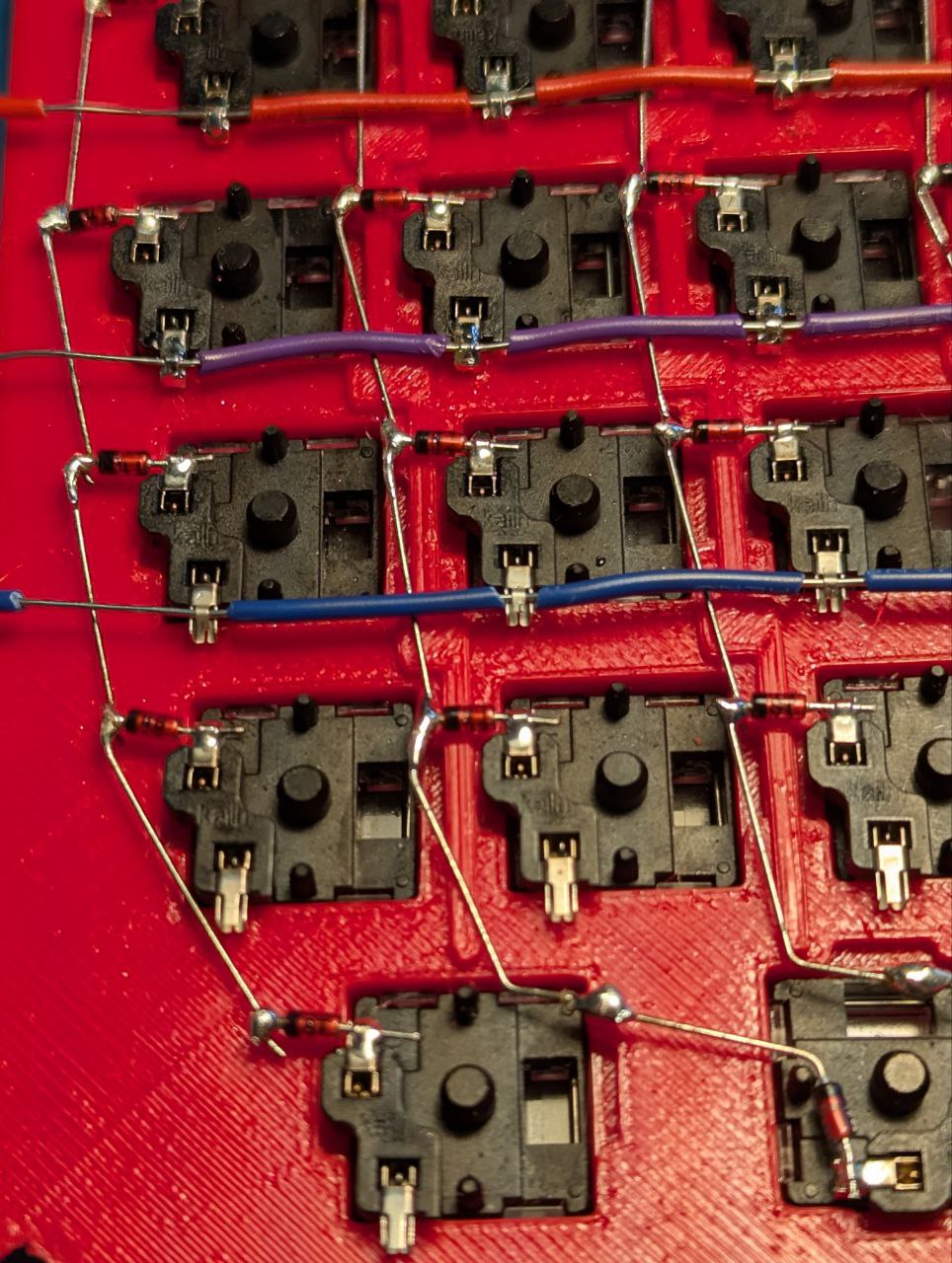 A close-up of the wiring, showing how the socket holds the wire.
So I was able to raise one of the channels, slide a wire in, and kind of crimp it around the wire, so that it was kept in place while I was soldering. This allowed me to go very much faster as well; less bending wires to make them fit tightly, and more bending the hotswap socket instead.
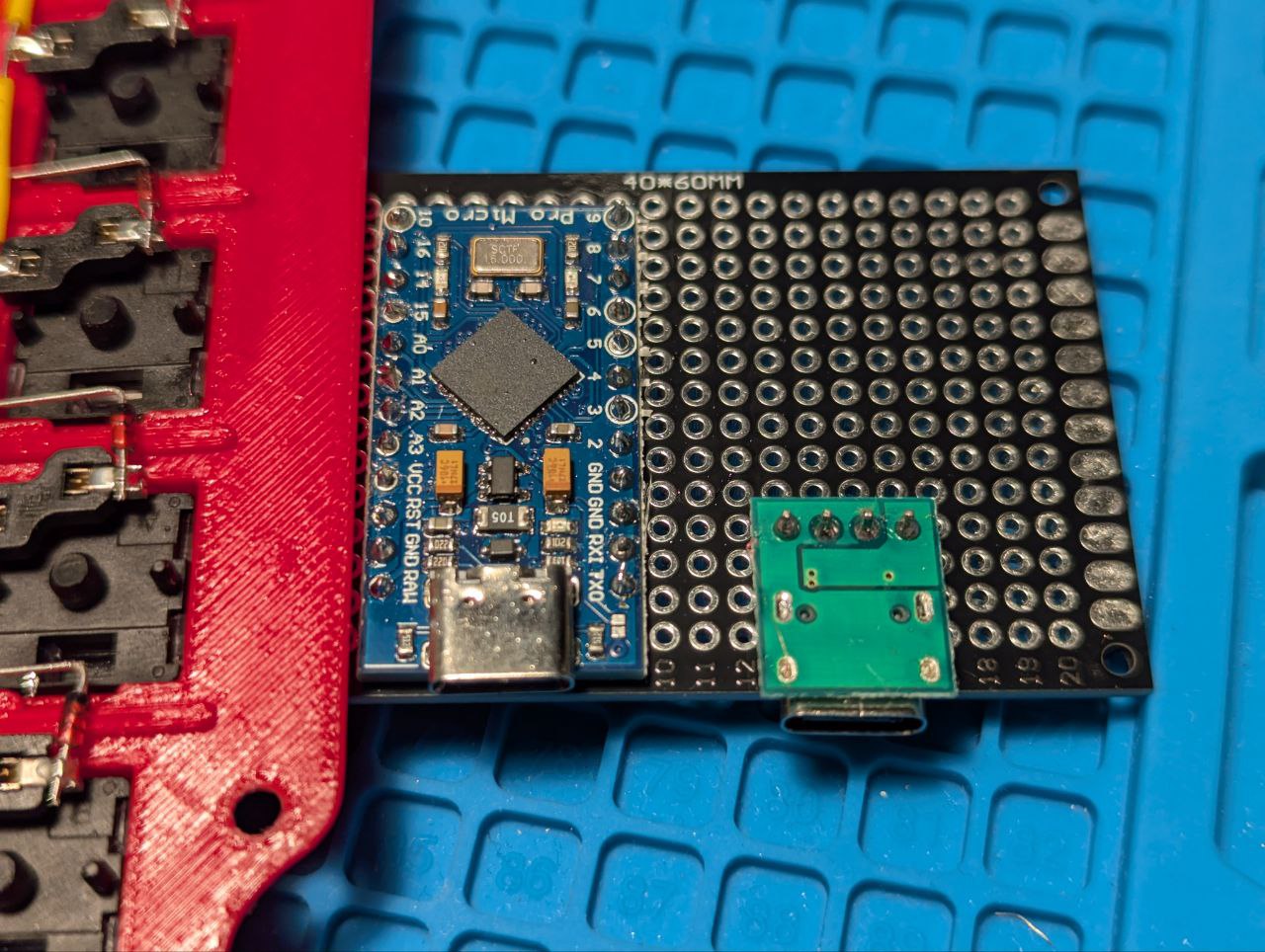 The PCB plate with the microcontroller and USB-C socket soldered on.
On the other side of things, I had also managed to solder the microcontroller and USB-C socket to my PCB plate. This turned out to be very useful during soldering, since I could move this around the board more easily, and it was easy to wire the microcontroller to the USB-C socket.
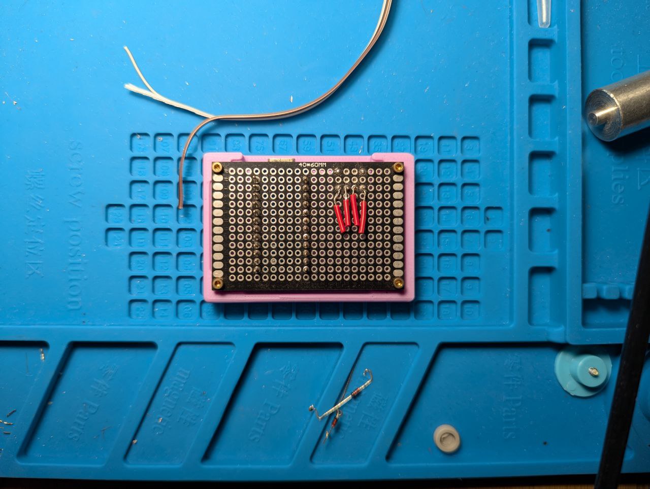
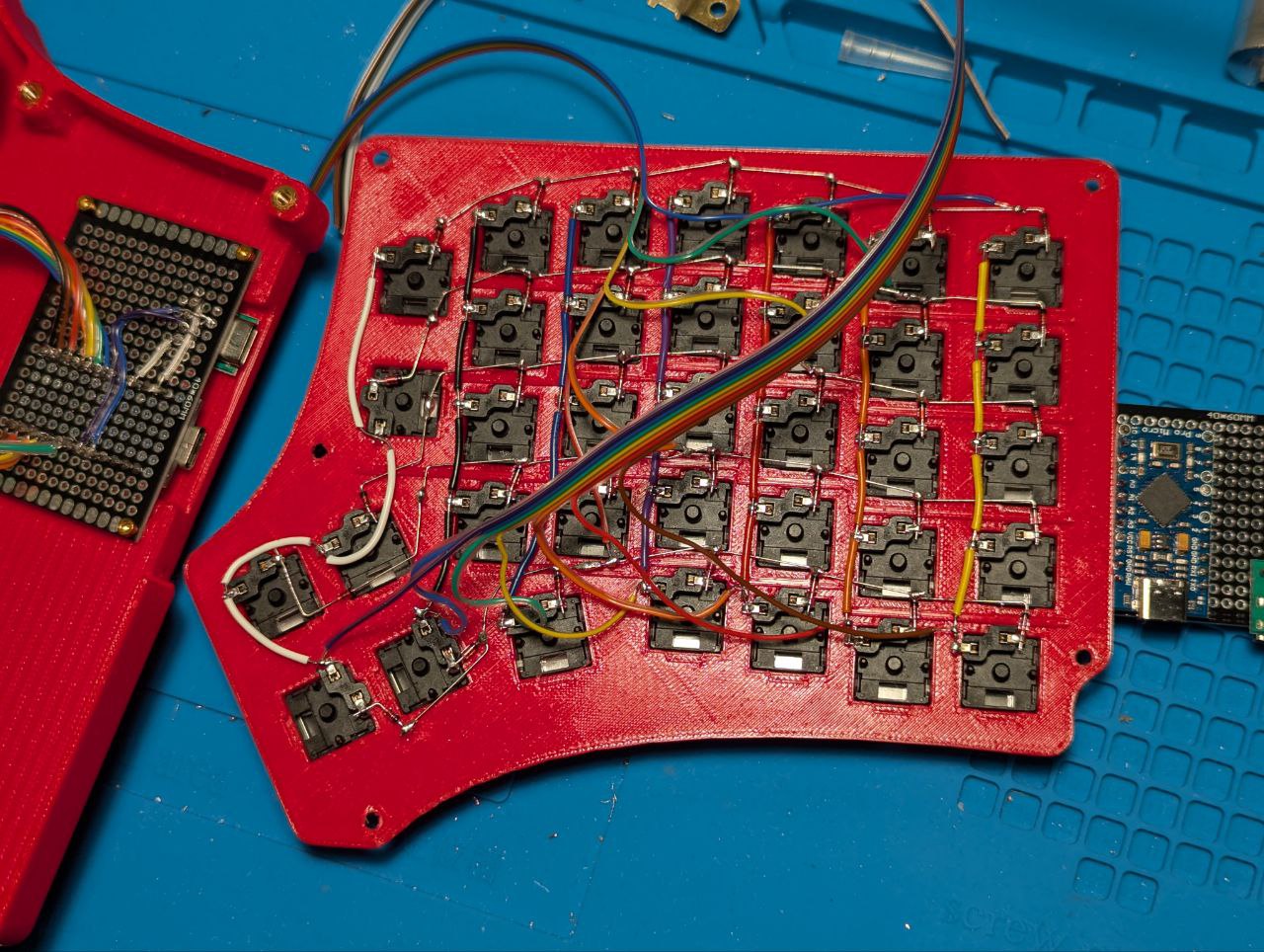 One half, partially wired.
Wiring was a bit simpler this time too, since I had experienced the trouble of having wires coming from too close to the microcontroller. So I opted to wire from as far away as possible, running to the microcontroller, to give the wires plenty of room to run around and sit wherever they could when the case was closed.
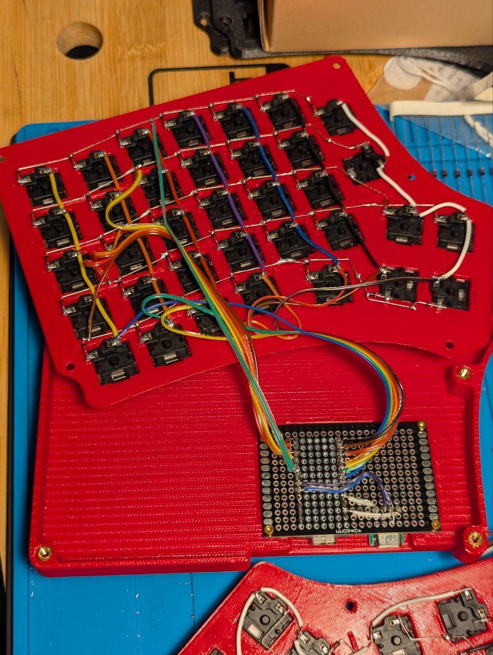 Finished internals of the right side.
Wiring these connections to the PCB Plate was relatively simple. It helped a bit that there was a plate keeping everything together; this made the wiring from the microcontroller to the USB-C very simple, and I could just use short wires and keep things tight, eliminating a bunch of unnecessary loose wires from the mix.
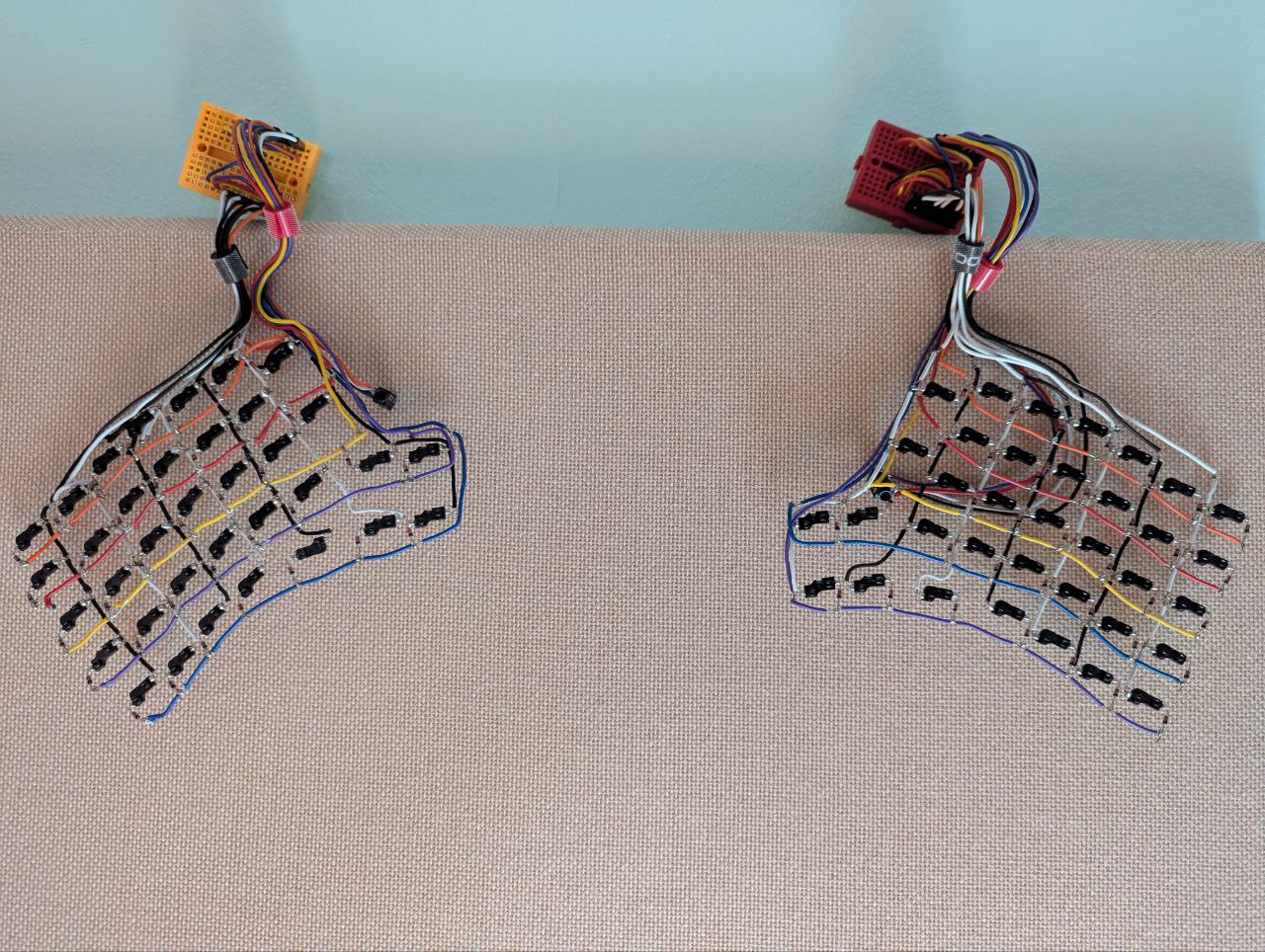
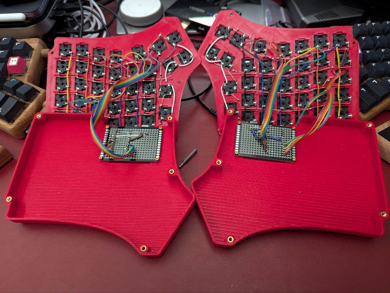 Finished internals of both halves.
One mistake I made while doing the left side was just assuming I could mirror the wiring. I forgot that I wasn’t flipping the microcontroller, so I couldn’t actually mirror; instead, I had mirrored the microcontroller and USB-C positions, but the pins were not mirrored. A short desoldering and re-soldering exercise later, I was able to get everything back in the right spot.
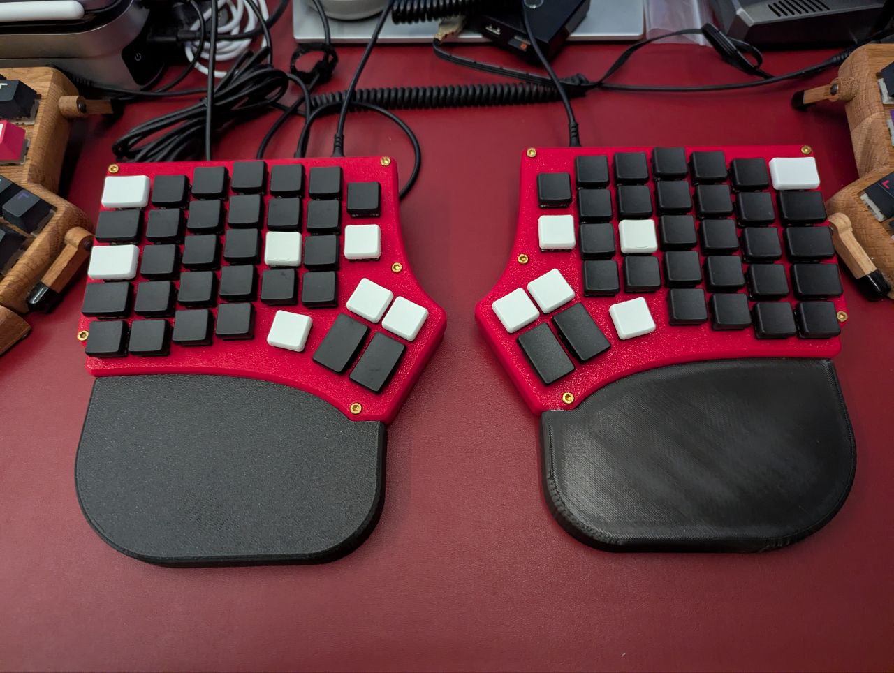
And finally, my latest creation!
The completed Redox Handwire V4!
I learned a lot more with this build, especially because I challenged myself to solve a few long-standing problems as I mentioned earlier.
Maybe the next one will be wireless? Let’s see.